In this project, I extended the functionality of Assignment 3-1 with a variety of important features such as the ability to render arbitrary materials and produce realistic lighting and camera effects. I began by implementing material scattering models for mirrors and glass, the former of which reflects light specularly and the latter of which both reflects and refracts light. Next, I developed BSDF functions to describe material properties using microfacets, enabling me to render diffuse and glossy metals of various kinds. To imbue the pathtracer with greater realism, I created support for environment lights, which provide more realistic lighting conditions for models within a scene. Lastly, I implemented a thin-lens model for the camera to allow depth of field effects by manipulating aperture and focal distance, making renders all the more realistic. One problem I encountered was properly focusing the thin-lens in the last part of the project, which I resolved by rendering only parts of the scene and tuning the camera parameters by hand to fix the focus plane properly.
Part 1: Mirror and Glass
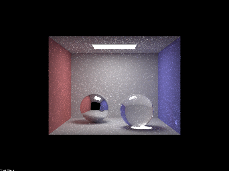
First, I implemented reflective and refractive materials, which allowed me to properly render mirror and glass spheres as shown below. For the implementation, I wrote a function to reflect an outgoing ray to an incoming ray, utilizing the function to implement sampling for the mirror BSDF. Next, I wrote a function to refract rays across media using Snell's law, utilizing this function, the reflection function, and Schlick's approximation for the relative effect of reflection and refraction to model the glass BSDF.

|
|
|
|

|
|
|
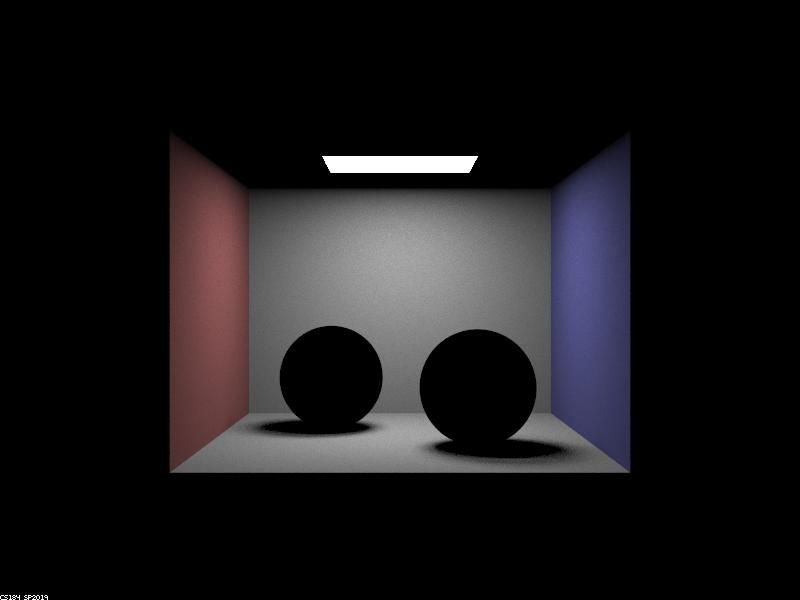
When the max ray depth is zero, the light in the image is solely the light entering the camera after zero bounces - that is, the light emitted directly from the area light source into the camera. There are no multibounce effects present as we can only see the light directly emitted by the source.
When the max ray depth is raised to one, we now see the walls and floor (but not the ceiling or the spheres). Because rays of light can bounce at most once, the light emitted from the area source bounces off the walls and into the camera as well as off the floor and into the camera. These are the only one-bounce effects that occur, which is why the walls and floor are the only elements that appear after increasing the max ray depth to one. The reason that no light reflects off the spheres and into the camera is because the staff solution makes the assumption that delta BSDFs have no direct lighting.
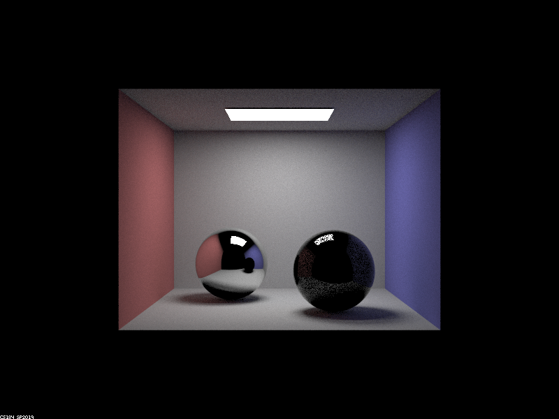
When the max ray depth is raised to two, the new multibounce effects are the reflections of the red and blue walls and floor as well as the area light source in both the mirror and glass spheres (although the reflection is much fainter in the latter). These reflections result from two bounces because light emitted from the area source bounces off the walls (or floor) towards the spheres and bounces off the spheres (perfect reflection) into the camera. Another two-bounce effect that appears is the visibility of the ceiling, which results from light bouncing off the walls, floor, or spheres towards the ceiling and then bouncing off the ceiling into the camera. Yet another is the red and blue light bouncing off the walls, bouncing off the floor, and into the camera. Lastly, we see a reflection of the glass sphere in the mirror sphere because in the reverse path, light entering the camera previously bounced off the mirror sphere and before that bounced off the glass sphere (which has no direct lighting).
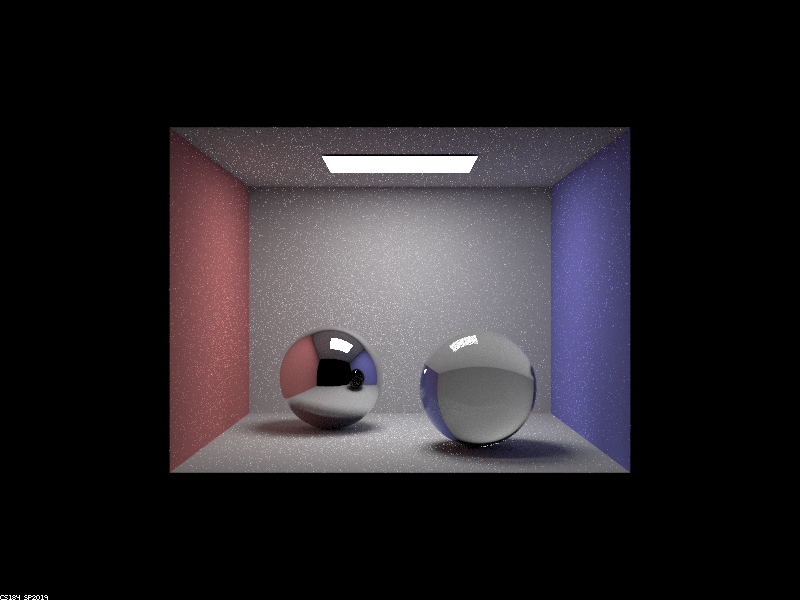
When the max ray depth is raised to three, the new multibounce effects are the reflection of the ceiling in the mirror sphere and the refraction of light from behind the glass sphere into the camera. The reflection of the ceiling in the mirror sphere occurs because light emitted from the source bounces once in the scene towards the ceiling, bounces off the ceiling towards the mirror sphere, and bounces off the mirror sphere into the camera, which takes three bounces at least. The refraction of light through the glass sphere also takes at least three bounces of light because light leaving the source must bounce off the floors or wall towards the glass sphere, refract into the interior of the glass sphere (one bounce), and refract to leave the glass sphere and enter the camera.
When the max ray depth is raised to four, the new multibounce effects are the patch of light under the glass sphere on the floor (reminiscent of caustics) and the fact that the reflection of the glass sphere in the mirror sphere is see-through. The patch of light only occurs after four bounces because when considering the reverse path, light entering the camera previously bounced off the floor under the glass sphere, which previously refracted out of the glass sphere, which previously refracted into the glass sphere, and one more light emitted from the source refracts into the interior of the glass sphere (one bounce), refracts out of the sphere (one bounce), and at this point one more indirect bounce is required because the glass's BSDF is delta and therefore does not receive direct light from the source. The other effect that appears, which is the reflection of the glass sphere in the mirror sphere being see-through, occurs only after four bounces because light emitted from the source bounces off the blue wall, refracts into the glass sphere, refracts out of the glass sphere, and reflects off the mirror sphere into the camera.
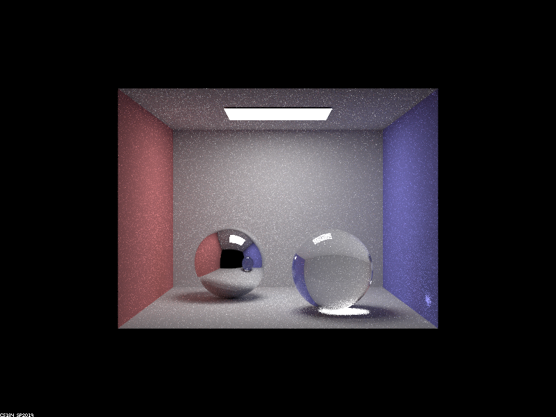
When the max ray depth is raised to five, the new multibounce effects are a patch of light on the blue wall and a patch of light on the underside of the glass sphere. Both these patches occur because the patch of light on the floor arising from four bounces reflects light rays that bounce off the blue wall and the underside of the glass sphere, respectively, which are reflected into the camera. This requires one more bounce of light than is needed to see the patch of light on the floor, so five bounces.
In the last image, when the max ray depth is 100, no significant multibounce effects appear. This is because the important multibounce effects can primarily be seen when the max ray depth is 5. Of course, there are some details in this image that are not present in the previous image such as subtle light refractions through the glass sphere that are reflected by the mirror sphere; such minutiae only arise after many, many bounces of light. Of course, when the max ray depth is 100, the global illumination estimator is more unbiased than when the max ray depth is 5, but the multibounce effects are largely the same.
Part 2: Microfacet Materials
Next, I implemented microfacet BRDFs in order to render materials with tunable properties. For the implementation, I started by appropriately defining the function outputting the value of the BRDF for certain incoming and outgoing rays, which is directly proportional to the Fresnel term and the normal distribution function and inversely proportional to the angles between the surface normal and the two rays. The normal distribution function, which describes the orientations of the microfacets' surface normals, was expressed using the Beckmann distribution, which can be varied using a parameter called alpha that controls the diffuseness. Again, I wrote a function to compute the Fresnel term (proportional to the amount of light reflected rather than refracted), but had to do so for red, green, and blue wavelengths of light because the materials in this part were conductors. Lastly, I implemented importance sampling for the normal distribution function, which entailed writing equations for the probability density of the Beckmann distribution.
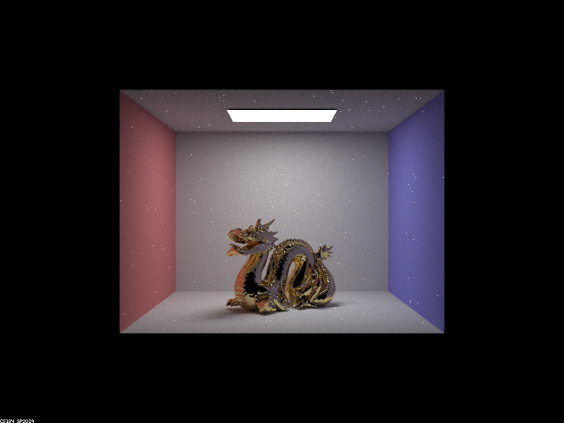
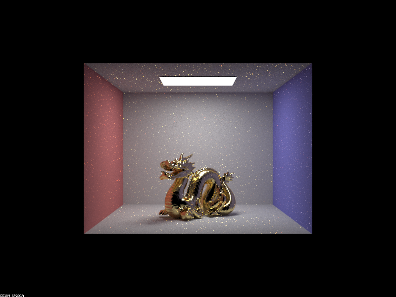
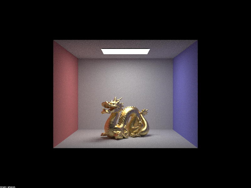
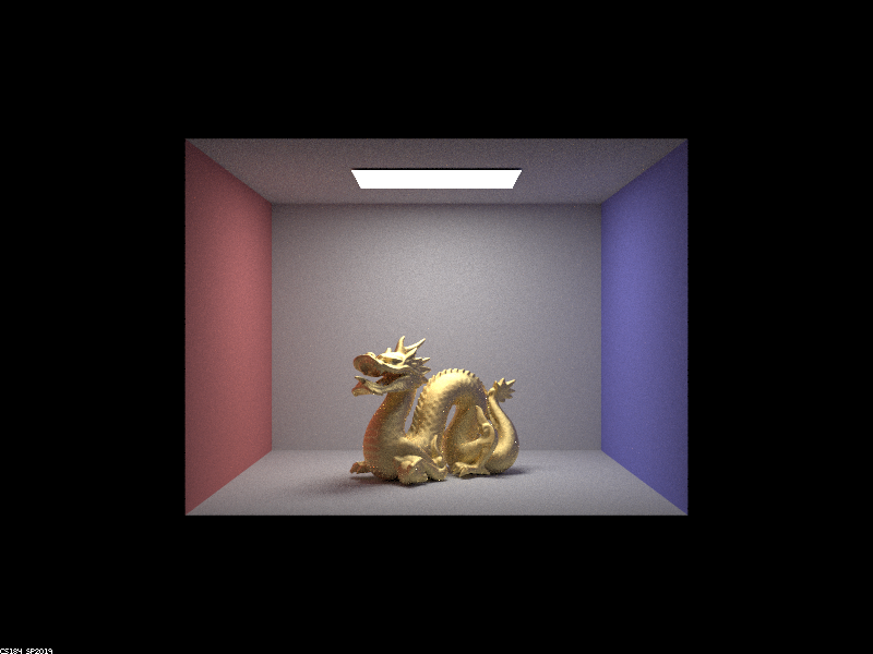
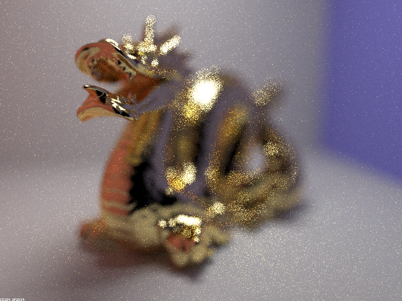
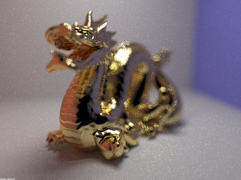
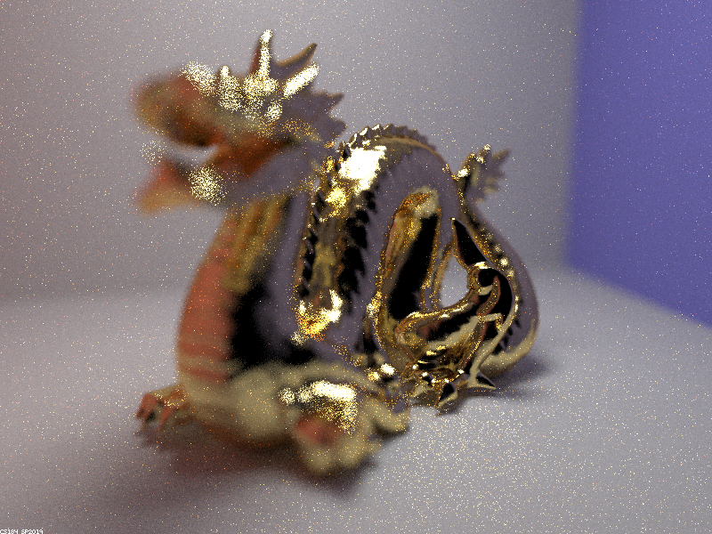
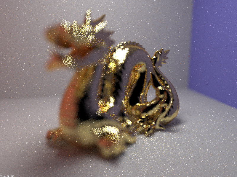
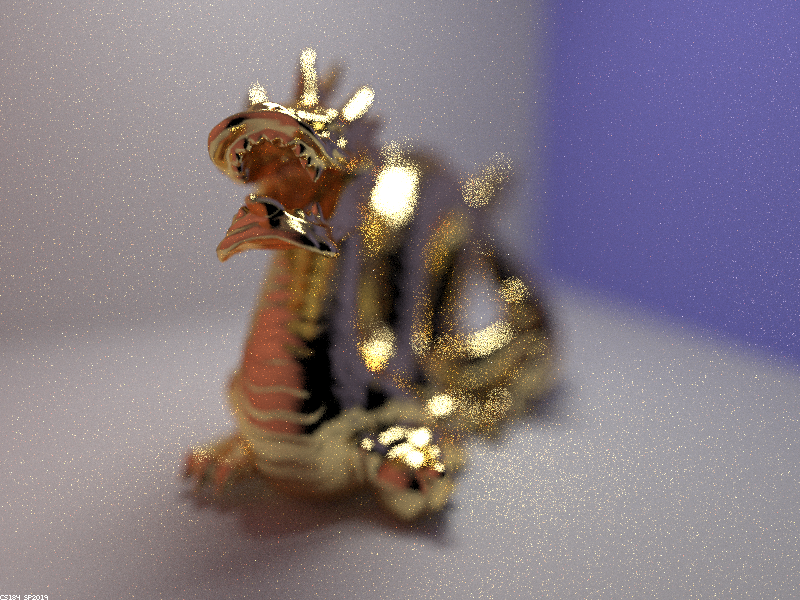
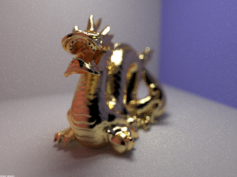
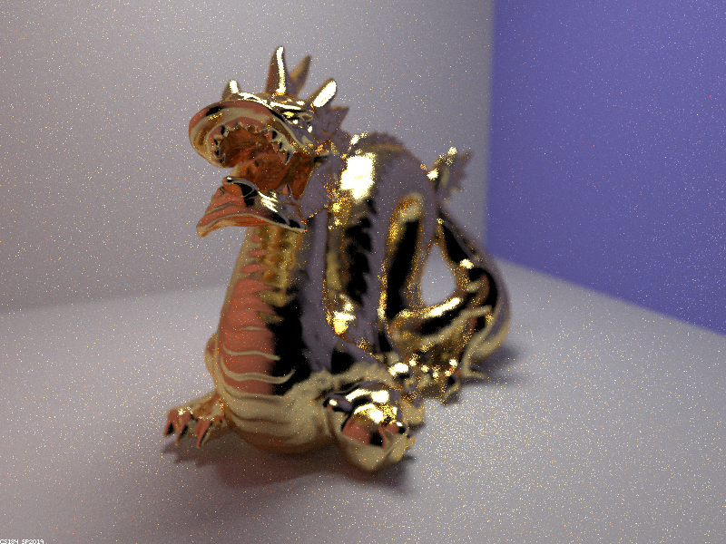
Below are four renderings of a dragon with microfacets corresponding to a gold surface. The value of parameter alpha was varied to derive surfaces with differing reflectance properties.
|
|
|
|
Above, varying alpha changes the relative smoothness of the surfaces. As alpha is increased, the microfacet BSDF for the dragon model becomes more and more diffuse, therefore reflecting light more equally in all directions and appearing "rougher" to the human eye. For smaller values of alpha, the dragon become glossier, reflecting light in a specular fashion - that is, more like a mirror. As a result, when alpha was set equal to 0.005, the surface of the dragon looked extremely smooth (and darker than for higher values of alpha because the glossy surface tends to reflect light coming from black areas outside the box).
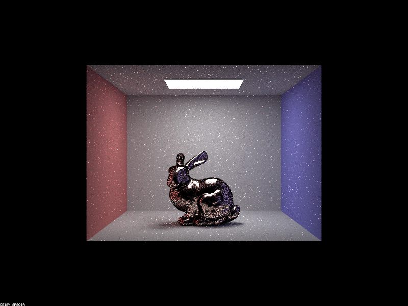
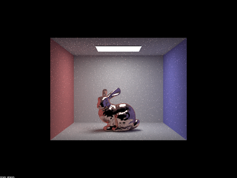
To speed up rendering and reduce aliasing, I implemented importance sampling for these microfacet BSDFs. Below are two images comparing cosine hemisphere sampling to importance sampling for a copper bunny model.
|
|
For the two images above, there was much more noise present when doing cosine hemisphere sampling when compared to importance sampling. This is because cosine hemisphere sampling computes secondary ray samples around uniformly about the hemisphere above the intersection point (taking into account Lambert's cosine law). Because cosine hemisphere sampling does not take into account the distribution of possible incoming rays that most heavily influence a given outgoing ray (in other words, the normal distribution function), there is a lot of noise in the reflective areas on the bunny. By contrast, importance sampling reduces noise dramatically and produces better reflections as it tends to select secondary rays that are most likely to reflect light in the direction of the outgoing ray.
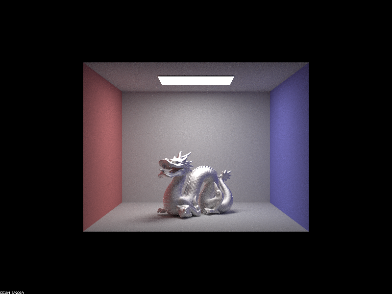
The power of microfacet BSDFs is that they can be tuned to produce a variety of material types. Below is the dragon model rendered with a zinc surface and diffuse BSDF. The appropriate eta values are (1.1181, 0.92678, 0.71515), and the k values are (5.5577, 4.9657, 4.1696).
|
Part 3: Environment Light
The idea behind environment lighting is that if we wish to place a 3D model in a real-world scene so that it looks like it's actually part of the scene, we can use a spherical environment map that approximates the light incident on the model from every direction. This environment map is essentially a 360 degree picture of a given setting, so to implement environment lighting, all we have to do is treat the map as a light source from which radiance can be reflected off the model. Instead of shooting rays that bounce off the model and onto a light, we observe where the secondary rays intersect the map and calculate irradiance on the model accordingly.
To implement environment lighting, I first wrote a function to transform secondary light rays into coordinates on the map. Next, I implemented uniform sampling, which involved generating a uniformly random spherical ray (representing a ray of light bouncing off the model), and computing the map's pixel value (with bilinear interpolation) as before. Finally, I implemented importance sampling to sample rays that were more likely to point to regions on the environment map with stronger intensities. This was done by calculating a probability density function on the map's rows and a conditional density function on the columns, using the normalized pixel intensities as constant-piecewise probability values.
The two-dimensional probability distribution for the environment map is shown below.

|
I used this generated probability distribution to perform importance sampling with the environment light. Below is a comparison of uniform sampling and importance sampling for the unlit bunny model.
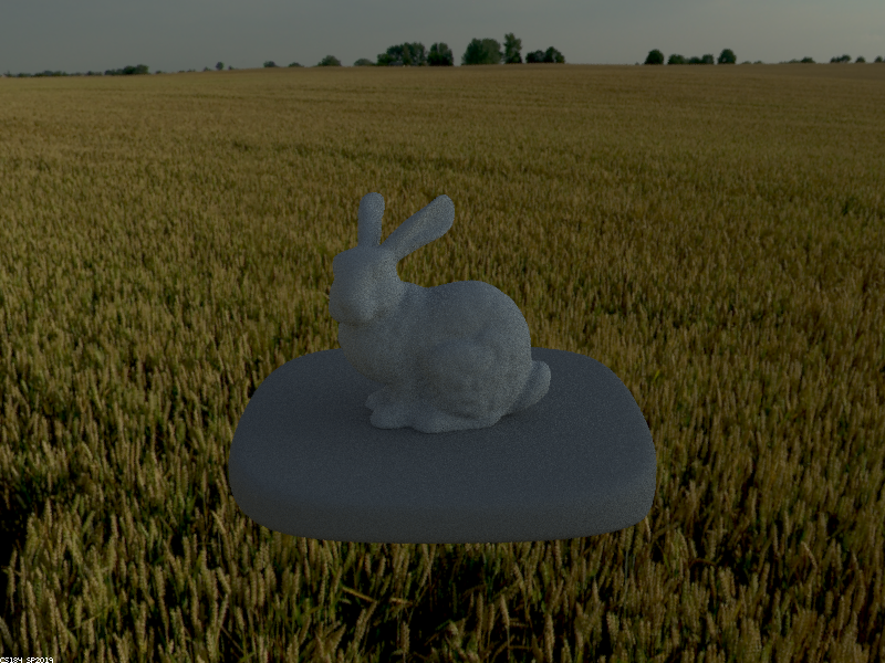
|
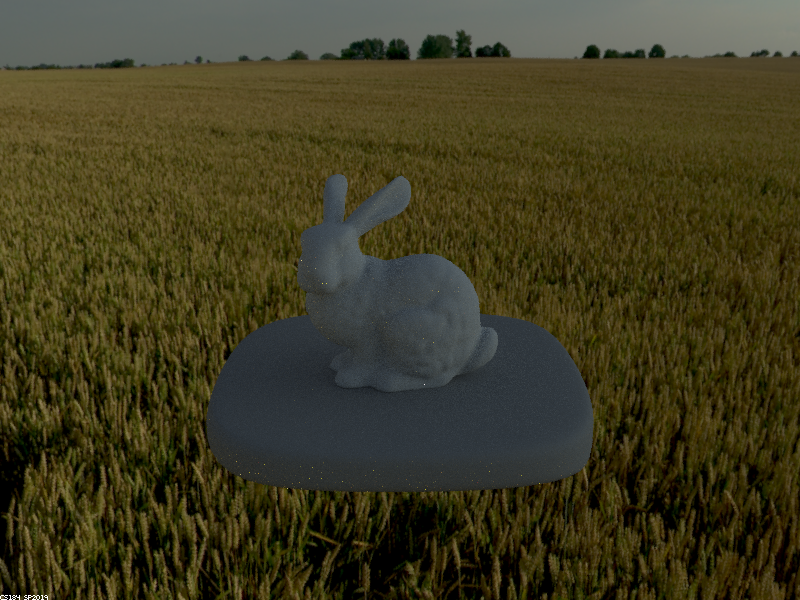
|
For the images above, the one produced with importance sampling has less noise in the lighter regions on the model, although it is difficult to pick up without zooming in as the surface is a bit dark. This occurs because importance sampling favors secondary rays that originate from map locations with more intense light, which are the most influential on the incident irradiance.
To further test importance sampling for the environment light, I compared uniform sampling and importance sampling for the microfacet bunny model as shown below.
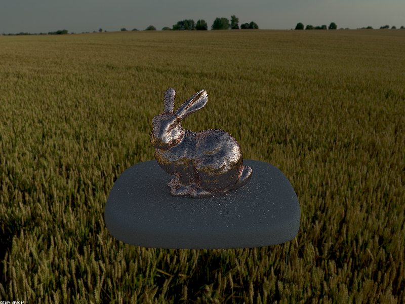
|

|
Once again, there is far less noise when we use importance sampling, as can be seen in the highlights on the bunny model in the images above. Specifically, the bunny's ear, side, and cheek highlights have less noise when using importance sampling as compared to cosine hemisphere sampling. Once again, this occurs because importance sampling favors secondary rays that originate from pixels on the map with more intense light, which influence the surface irradiance more.
Part 4: Depth of Field
The key difference between the pinhole and thin-lens camera models is that in the pinhole model, we imagine light rays from the scene entering through an infinitesimal hole and striking the image plane within certain pixels. Thus, the rays of light bouncing off a point on an object and traveling through the pinhole can only affect a single pixel on the image plane, meaning every visible point on each object is in focus. On the other hand, in the thin-lens model, light rays from the scene strike an infinitesimally thin lens with finite radius, refract, and then strike a pixel on the image plane. Light rays leaving a point on a surface can refract through the thin lens and potentially strike many different pixels on the image plane, creating focus blur and enabling depth of field effects. Only objects residing at exactly the lens's focal distance are perfectly in focus, as light rays from these objects refract and strike the same pixel on the image.
To implement the thin-lens model, for each pixel, I shot multiple rays going through that pixel and striking a random point on the area of the lens (which is a disc), and then using the laws of refraction to shoot a refracted ray into the scene.
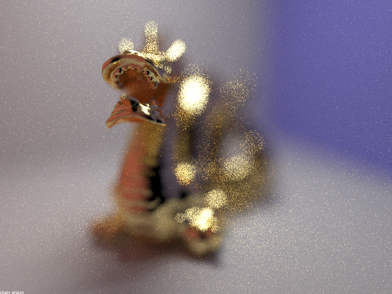
Below is a focus stack showing how the thin-lens model can focus on different parts of a scene.
|
|
|
|
As the focal distance increases, parts of the dragon that are further away from the lens come into focus because the plane of focus translates further from the lens. As explained before, only points on the focus plane are perfectly in focus, so light rays from other points on the dragon refract through the lens and land on several pixels on the image plane, leading to defocus blur.
Another interesting test for the thin-lens model is to vary the aperture (lens radius) while focusing on the same point in the scene. For each succesive image below, the aperture was halved.
|
|
|
|
As seen above, the smaller the aperture, the more the lens resembles a pinhole camera, meaning more of the scene comes into focus. The first image corresponds to the largest aperture and therefore has the shallowest depth of field.